Technical Guidelines to Professional Groundwater Production Well Construction
Professional Groundwater Production Well Construction: Comprehensive Step-by-Step Technical Guidelines, Standards Compliance, Quality Assurance Protocols, and Commissioning Procedures for High-Capacity Potable Water Supply Systems in Indonesia
Reading Time: 75 minutes
Key Highlights
• Comprehensive International Standards: Professional groundwater well construction follows standards from AWWA (American Water Works Association) A100-21, NGWA (National Ground Water Association) Water Well Construction Standard 01-14, EPA design guidelines, and Indonesian SNI 6469:2012, establishing technical requirements for site assessment, drilling methods, casing installation, annular sealing, well development, and performance testing ensuring decades-long reliable water supply
• Critical Construction Phases: Complete well development progresses through seven distinct phases spanning preliminary site investigation and hydrogeological assessment (2-6 weeks), detailed design and permitting (3-8 weeks), drilling operations and geological logging (1-4 weeks depending on depth 50-300 meters), casing and screen installation with precision alignment (2-5 days), grout sealing preventing contamination (1-2 days curing), well development achieving 150-300% design yield (3-7 days), and comprehensive performance testing including 24-72 hour pumping tests establishing sustainable capacity
• Quality Assurance Requirements: High-standard well construction demands continuous quality control including daily drilling logs documenting lithology every 0.5-1.0 meter depth intervals, video camera inspection verifying casing integrity and screen placement, geophysical logging (natural gamma, resistivity, spontaneous potential) characterizing aquifer properties, water quality sampling at multiple depths during drilling confirming potability, and certified testing by accredited laboratories meeting ISO 17025 standards for bacteriological, chemical, and physical parameters
• Performance and Economics: Properly constructed production wells achieve specific capacities typically 5-50 m³/hour per meter drawdown depending on aquifer characteristics, operational lifespans exceeding 25-40 years with appropriate maintenance, construction costs ranging IDR 8,000,000-25,000,000 per meter depth (USD 500-1,600/meter) including materials, drilling, testing and commissioning, and lifecycle cost advantages delivering water at IDR 800-2,500 per cubic meter (USD 0.05-0.16/m³) significantly below treated surface water alternatives for suitable hydrogeological conditions
Executive Summary
Professional groundwater production well construction represents sophisticated engineering undertaking requiring integration of hydrogeological sciences, advanced drilling technologies, materials engineering, quality assurance protocols, and regulatory compliance frameworks to deliver reliable, safe, and economically sustainable water supply systems serving municipal utilities, industrial facilities, commercial developments, and rural communities throughout Indonesia. The technical complexity of modern well construction has developed substantially from historical hand-dug wells or simple borehole drilling, now incorporating precision drilling methods achieving depths 50-300+ meters, sophisticated completion techniques utilizing engineered casing and screen assemblies preventing aquifer collapse while optimizing hydraulic efficiency, specialized grouting materials and placement methods ensuring sanitary protection against surface contamination, comprehensive development procedures removing drilling-induced formation damage maximizing well productivity, and testing protocols establishing reliable performance characteristics supporting decades-long operational planning and regulatory compliance demonstrations.
Indonesian groundwater resources provide essential water supply supporting approximately 60-70% of national domestic water consumption, with hundreds of thousands of production wells ranging from small-diameter household wells under 10 meters depth to large municipal supply wells exceeding 200 meters depth and capacities surpassing 100 liters per second, collectively abstracting estimated 15-25 billion cubic meters annually from diverse aquifer systems including volcanic rock formations, alluvial deposits, limestone karst, and sedimentary basins distributed across Indonesian archipelago's complex geological settings. However, groundwater quality and availability face increasing pressures from urbanization, industrial development, agricultural intensification, and climate variability affecting recharge patterns, creating urgent need for professional well construction practices ensuring optimal aquifer utilization while protecting groundwater resources through proper well design preventing contamination, appropriate capacity management avoiding over-extraction causing aquifer depletion or saltwater intrusion in coastal areas, and comprehensive monitoring enabling adaptive management responding to changing conditions maintaining long-term resource sustainability.
This comprehensive technical analysis provides detailed step-by-step guidance for professional groundwater production well construction following international best practices from American Water Works Association (AWWA) standards including A100-21 Water Wells specification, National Ground Water Association (NGWA) Water Well Construction Standard 01-14, United States Environmental Protection Agency (EPA) groundwater monitoring well design and installation guidelines, United States Department of Agriculture Natural Resources Conservation Service (USDA NRCS) water well standard Code 642, military specifications including Unified Facilities Guide Specifications (UFGS) 33 11 13 for potable water supply wells, and Indonesian national standards particularly SNI 6469:2012 on deep well construction, integrated with practical implementation guidance addressing site-specific challenges common in Indonesian hydrogeological and operational contexts including heterogeneous aquifer conditions, complex permitting requirements, equipment availability constraints, quality control implementation, and commissioning verification procedures.
The document structure follows logical well development sequence through seven comprehensive phases: (1) Preliminary Investigation and Site Assessment establishing hydrogeological conditions, regulatory requirements, and conceptual well design; (2) Detailed Design and Engineering producing complete construction specifications, material selections, and quality assurance plans; (3) Permitting and Pre-Construction encompassing regulatory approvals, contractor selection, and site preparation; (4) Drilling Operations including method selection, geological logging, and safety management; (5) Well Completion comprising casing installation, screen placement, and grout sealing; (6) Well Development and Testing through airlifting or pumping removing formation damage and establishing performance; and (7) Commissioning and Documentation finalizing installations through comprehensive testing, system integration, and regulatory acceptance. Each phase receives detailed technical treatment covering objectives, methodologies, quality standards, common challenges, and verification procedures, supplemented by process flow diagrams, technical specifications tables, quality checklists, and decision frameworks supporting informed implementation by engineering consultants, drilling contractors, well owners, and regulatory agencies involved in groundwater development projects across Indonesian water supply sector.
Phase 1: Preliminary Investigation and Hydrogeological Site Assessment
Preliminary investigation constitutes critical foundation for successful well construction, establishing essential understanding of hydrogeological conditions, regulatory constraints, site access logistics, and conceptual design parameters guiding subsequent detailed engineering and construction phases. This phase typically requires 2-6 weeks depending on site complexity, data availability, and investigation scope, with activities conducted by qualified hydrogeologists or groundwater engineers holding appropriate professional certifications and supported by experienced field personnel conducting geophysical surveys, exploratory drilling where necessary, and comprehensive desktop studies synthesizing available geological, hydrological, and water quality information applicable to project location.
Desktop hydrogeological assessment initiates investigation through systematic compilation and analysis of existing geological and hydrogeological data characterizing project area aquifer systems, recharge sources, groundwater flow patterns, water quality baseline conditions, and existing well performance providing analogous information supporting conceptual understanding and preliminary design decisions. Key information sources include Indonesian Geological Agency (Badan Geologi) geological maps and publications documenting regional stratigraphy and structure, published hydrogeological studies from research institutions or consultants characterizing local aquifer properties, government databases including Ministry of Public Works and Housing (PUPR) water resources information systems containing well inventory data, academic research from university departments investigating groundwater systems, and proprietary information from operating wells in vicinity where owners consent to data sharing supporting regional understanding.
Figure 1: Complete Well Development Process Flow - Seven Phase Framework
Professional Groundwater Production Well
Complete Development Framework: Site Investigation to Commissioning
Phase 1: Preliminary Investigation (2-6 weeks)
→ Desktop hydrogeological assessment & data compilation
→ Geophysical survey (resistivity/seismic) mapping aquifer
→ Exploratory test drilling & aquifer sampling (if required)
→ Regulatory review & preliminary permit requirements
→ Conceptual well design & yield estimation
Deliverables: Site investigation report, aquifer characterization, conceptual design
↓
Phase 2: Detailed Design & Engineering (3-8 weeks)
→ Final well design: depth, diameter, casing/screen schedule
→ Material specifications (casing, grout, filter pack)
→ Construction method selection & equipment requirements
→ Quality assurance/quality control (QA/QC) plan
→ Cost estimation & procurement specifications
Deliverables: Construction drawings, technical specifications, QA plan
↓
Phase 3: Permitting & Pre-Construction (2-12 weeks)
→ Groundwater extraction permit (izin pengambilan air tanah)
→ Environmental compliance documentation
→ Contractor qualification & equipment verification
→ Site preparation & access establishment
→ Pre-construction meeting & mobilization
Deliverables: All permits, approved contractor, prepared site
↓
Phase 4: Drilling Operations (1-4 weeks)
→ Mobilization drilling rig & support equipment
→ Pilot hole drilling with continuous geological logging
→ Geophysical logging (gamma, resistivity, caliper)
→ Water quality sampling at target aquifer depths
→ Borehole reaming to final diameter (if required)
Deliverables: Driller's log, geophysical logs, aquifer test data
↓
Phase 5: Well Completion (2-5 days + curing)
→ Casing installation with alignment verification
→ Well screen placement at aquifer zones
→ Filter pack (gravel pack) placement around screen
→ Annular grout seal installation (surface to 15-30m minimum)
→ Surface seal & wellhead completion
Deliverables: As-built construction record, video inspection log
↓
Phase 6: Development & Testing (3-7 days)
→ Well development (airlifting, surging, high-velocity pumping)
→ Step-drawdown test (3-5 steps, 1-2 hours each)
→ Constant-rate pumping test (24-72 hours minimum)
→ Recovery monitoring & aquifer analysis
→ Water quality comprehensive testing
Deliverables: Test reports, aquifer parameters, yield certification
↓
Phase 7: Commissioning & Handover (1-2 weeks)
→ Pump installation & electrical connection
→ System integration & control setup
→ Final water quality certification
→ Documentation package completion
→ Operator training & maintenance manual
→ Regulatory inspection & acceptance
Outcome: Fully Operational Production Well Ready for Service
Total Project Duration: Typically 10-18 weeks from investigation to commissioning
Construction Duration: 2-6 weeks for drilling through development
Key Success Factors: Qualified team, proper equipment, QA/QC, adequate testing
Geophysical surveys provide non-invasive investigation methods characterizing subsurface conditions including aquifer depth, thickness, lateral extent, and water quality indicators supporting well siting decisions and preliminary design parameters. Electrical resistivity surveys represent most common geophysical method for groundwater investigations, utilizing electrode arrays measuring subsurface electrical resistivity that correlates with geological materials, with low resistivity typically indicating clay-rich formations or saline water while high resistivity suggests sandy or gravelly aquifers containing fresh water. Vertical Electrical Sounding (VES) provides one-dimensional subsurface model beneath measurement station suitable for relatively homogeneous geological settings, while Electrical Resistivity Tomography (ERT) creates two-dimensional cross-sections ideal for complex geology with lateral variations. Seismic refraction surveys measure propagation velocities of elastic waves through subsurface materials, with velocity contrasts identifying geological boundaries including water table depth, bedrock interface, and consolidated versus unconsolidated sediments, proving particularly valuable in hard rock terrains where electrical methods face interpretation challenges from resistive crystalline rocks.
Table 1: Preliminary Investigation Checklist and Data Requirements
| Investigation Component | Required Data/Activities | Information Sources | Expected Outcome |
|---|---|---|---|
| Desktop Hydrogeology | Regional geology, aquifer types, groundwater flow direction, recharge areas, existing well data within 1-5 km radius | Geological Agency maps, PUPR databases, research papers, local well records | Conceptual hydrogeological model, target aquifer identification |
| Water Quality Baseline | Existing well water quality data: bacteriological, chemical (major ions, metals, nutrients), physical parameters | Nearby well sampling, health department records, previous studies | Expected water quality, treatment needs assessment |
| Regulatory Requirements | Groundwater extraction permit requirements, protected zones, environmental regulations, local ordinances | Provincial ESDM office, environmental agency, municipal planning | Permit pathway, compliance requirements, timeline estimates |
| Site Conditions | Topography, access routes, land ownership, utilities (power, water), environmental sensitivities, flood risk | Site visits, cadastral records, topographic maps, utility as-builts | Site suitability confirmation, access planning, logistics |
| Geophysical Survey | Resistivity survey (VES/ERT) 3-5 stations, or seismic refraction if bedrock site, interpretation report | Contracted geophysical survey firm, qualified geophysicist interpretation | Aquifer depth estimate ±10-20%, thickness, lateral continuity |
| Exploratory Drilling | Optional test boring 100-150mm diameter to target depth, continuous sampling, basic pumping test | Drilling contractor, on-site geological logging, pump test analysis | Confirmed aquifer properties, lithology, yield estimate |
| Yield Estimation | Preliminary specific capacity from analogous wells, transmissivity estimates, sustainable yield calculation | Regional well data analysis, aquifer test interpretation, modeling | Expected well capacity range, design flow rate selection |
| Conceptual Design | Preliminary well depth, diameter, casing/screen configuration, construction method recommendation | Engineering analysis integrating all investigation data | Design basis for detailed engineering, cost estimate input |
Note: Investigation scope and intensity scale with project size, investment value, and site complexity. Minimum desktop assessment and site visit essential all projects; geophysical survey recommended most projects; exploratory drilling justifiable high-capacity municipal/industrial wells or geologically uncertain sites.
Phase 2: Detailed Design and Engineering Specifications
Detailed design phase translates preliminary investigation findings and conceptual well design into comprehensive construction specifications, material selections, quality assurance protocols, and procurement documents enabling competitive contractor bidding and quality construction oversight. This engineering phase typically requires 3-8 weeks depending on well complexity, with experienced well design engineers producing complete drawing sets, technical specifications, and construction quality plans meeting applicable standards including AWWA A100-21 design criteria, NGWA construction standards, SNI 6469:2012 requirements for Indonesian applications, and project-specific performance objectives established through collaboration among well owner, hydrogeological consultant, and operations personnel who will ultimately manage completed facility.
Well depth and diameter selections represent fundamental design decisions profoundly affecting construction costs, operational performance, and long-term sustainability. Target well depth must penetrate sufficiently into productive aquifer(s) accessing adequate saturated thickness ensuring reliable yield under anticipated pumping conditions while accounting for seasonal water table fluctuations and potential long-term regional groundwater level declines from cumulative groundwater development, typically incorporating 10-30 meter penetration into principal aquifer below anticipated pumping level providing adequate submergence for pump intake preventing air entrainment, cavitation, or pump damage from insufficient Net Positive Suction Head (NPSH). Borehole diameter selection depends primarily on required pump capacity and desired annular space accommodating casing, screen, and grout placement, with typical production well diameters ranging 150-400mm (6-16 inch) for capacities 5-100 liters per second, following general guideline that borehole diameter should exceed pump bowl assembly diameter by minimum 50-75mm (2-3 inches) allowing adequate filter pack thickness and installation clearance.
Table 2: Production Well Diameter Selection Guidelines Based on Design Capacity
| Design Capacity (L/s) |
Design Capacity (m³/hour) |
Typical Pump Bowl Diameter |
Minimum Borehole Diameter |
Recommended Casing Diameter |
Typical Application |
|---|---|---|---|---|---|
| 2-5 | 7-18 | 4 inch (100mm) | 6 inch (150mm) | 4-5 inch (100-125mm) | Domestic supply, small hotel, light commercial |
| 5-10 | 18-36 | 5-6 inch (125-150mm) | 8 inch (200mm) | 6 inch (150mm) | Apartment complex, mid-size hotel, small industry |
| 10-20 | 36-72 | 6-8 inch (150-200mm) | 10 inch (250mm) | 8 inch (200mm) | Large commercial, industrial facility, small municipal |
| 20-40 | 72-144 | 8-10 inch (200-250mm) | 12 inch (300mm) | 10 inch (250mm) | Municipal supply, major industrial, large development |
| 40-70 | 144-252 | 10-12 inch (250-300mm) | 14 inch (350mm) | 12 inch (300mm) | Municipal supply well, regional water utility |
| 70-100+ | 252-360+ | 12-14 inch (300-350mm) | 16 inch (400mm) | 14 inch (350mm) | Major municipal supply, high-capacity industrial |
Notes: Diameters shown are nominal sizes; actual dimensions vary by manufacturer and standards (AWWA, API, metric). Larger diameters enable higher yields, accommodate larger pumps, provide operational flexibility, but increase drilling and completion costs proportionally. Select diameter based on long-term capacity needs accounting for potential future expansion, not just initial demand.
Casing and screen material selection critically impacts well longevity, water quality, and lifecycle costs, with choices driven by water chemistry characteristics particularly pH and dissolved constituents affecting corrosion potential, required service life expectations typically 25-40+ years for production wells, structural requirements resisting collapse from external earth pressures and handling loads during installation, hydraulic performance especially screen open area and entrance velocity, and economic considerations balancing initial costs against maintenance and replacement implications. Steel casing including carbon steel, low-alloy steel, and stainless steel grades dominated traditional well construction offering high strength and durability, with carbon steel remaining cost-effective choice for neutral to slightly alkaline, non-corrosive groundwater when protected by coatings or cathodic protection, though vulnerable to corrosion in acidic or aggressive water conditions limiting service life potentially to 10-20 years without protection. Polyvinyl chloride (PVC) and high-density polyethylene (HDPE) thermoplastic materials increasingly preferred for corrosive groundwater environments providing excellent chemical resistance, lighter weight simplifying handling and installation, smooth interior surface reducing friction losses and encrustation potential, and typical service lives exceeding 50 years, though requiring careful attention to pressure ratings, thread quality, and ultraviolet protection if exposed surfaces exist.
Screen design encompasses critical specifications including slot size, open area percentage, and screen length determining well hydraulic efficiency and sand control effectiveness. Slot size selection depends primarily on aquifer grain size distribution with fundamental principle that screen openings should retain 85-90% of formation material while passing 10-15% finer fraction, established through sieve analysis of representative formation samples collected during test drilling or from analogous wells, with typical slot sizes ranging 0.25mm (0.010 inch) for very fine sands to 3.0mm (0.120 inch) for coarse gravel aquifers. Screen open area expressed as percentage of total screen surface available for water entry should maximize hydraulic efficiency while maintaining structural integrity, with continuous-slot wire-wound screens achieving 8-12% open area, slotted pipe screens typically 3-6% open area, and specially designed high-open-area screens reaching 15-25% through advanced manufacturing, translating directly to entrance velocity where lower velocities below 0.05 m/s (0.15 ft/s) minimize head losses and reduce sand pumping risks. Screen length determination balances competing objectives of maximizing specific capacity through greater aquifer contact against concentrating drawdown which can induce vertical flow components carrying fines, with general guidance suggesting screen length should be 50-80% of productive aquifer thickness for confined aquifers, 30-50% for unconfined aquifers maintaining adequate saturated thickness above screen, positioned to optimize hydraulic efficiency while avoiding low-permeability zones or poor-quality water intervals.
Phase 3: Permitting, Contractor Selection, and Pre-Construction
Permitting and pre-construction phase encompasses securing required regulatory approvals, selecting qualified drilling contractor through competitive procurement, finalizing site preparations, and conducting pre-construction coordination ensuring all parties understand project requirements, quality expectations, safety protocols, and communication procedures. Duration varies substantially from 2-12 weeks depending primarily on permit processing timelines, procurement method, and administrative efficiency, with streamlined private sector projects potentially completing faster than government-funded works requiring extensive competitive bidding procedures.
Groundwater extraction permits (izin pengambilan dan pemanfaatan air tanah) constitute primary regulatory requirement under Indonesian water resources law, administered by provincial Energy and Mineral Resources (ESDM) offices or designated water resources agencies depending on provincial organizational structure and withdrawal volume, with permit application requiring substantial technical documentation including hydrogeological assessment report, well design specifications, predicted drawdown and radius of influence calculations, water balance demonstrating sustainable extraction not depleting aquifer or impacting neighboring wells, water quality baseline data, environmental management plan if extraction exceeds threshold volumes typically 50-100 m³/day varying by province, and proof of land ownership or authorization for well installation. Permit review and approval timelines range 1-3 months for routine applications increasing to 6+ months if environmental impact assessment (AMDAL) or public consultation requirements triggered by large withdrawals, location in protected zones, or identified stakeholder concerns requiring resolution through administrative process.
Critical Success Factor: Qualified Drilling Contractor Selection
Essential Contractor Qualifications and Evaluation Criteria:
1. Technical Capability and Experience:
- Minimum 5-10 years water well drilling experience, demonstrated portfolio completing similar wells (depth, diameter, geological conditions)
- Qualified drillers holding NGWA Certified Driller or equivalent credentials demonstrating professional competency
- Geological logging capability with experienced geologist or trained driller systematically documenting lithology
- References from recent projects (minimum 3-5) with owner contact information enabling verification of performance quality
2. Equipment Adequacy and Condition:
- Drilling rig with capacity exceeding project requirements (depth, hole diameter, torque, pull-back force) by safety margin 20-30%
- Appropriate drilling method capability (rotary, reverse circulation, air rotary, DTH hammer) matching geological conditions
- Well-maintained equipment evidenced through maintenance records, visual inspection, operational demonstration
- Adequate support equipment including mud pumps, compressors, generators, casing handling tools, grout mixing/pumping
- Safety equipment and fall protection for mast operations complying with occupational health and safety regulations
3. Quality Assurance and Documentation:
- Demonstrated QA/QC procedures including material inspection, installation verification, testing protocols documentation
- Daily drilling logs recording depth, lithology, drilling parameters (penetration rate, fluid returns, cuttings description)
- Material traceability system ensuring casing, screen, grout meet specifications with certified mill test reports
- Well construction record (as-built drawing) accurately documenting final configuration for owner and regulatory records
4. Financial and Legal Standing:
- Valid business licenses and drilling permits required under Indonesian regulations
- Financial capacity demonstrated through bank references, financial statements, or bonding capability
- General liability insurance covering third-party property damage, personal injury, environmental contamination
- Workers compensation insurance or social security contributions protecting employees
- Willingness to provide performance bond or warranty on completed well (typical 12-24 months on construction, separate from pump warranty)
Evaluation Approach: Use weighted scoring matrix evaluating qualifications (30%), technical proposal quality (25%), relevant experience (20%), equipment capability (15%), and price competitiveness (10%), avoiding sole focus on lowest bid which frequently correlates with corners cut, substandard materials, or inadequate expertise compromising well performance and longevity.
Phase 4: Drilling Operations and Geological Documentation
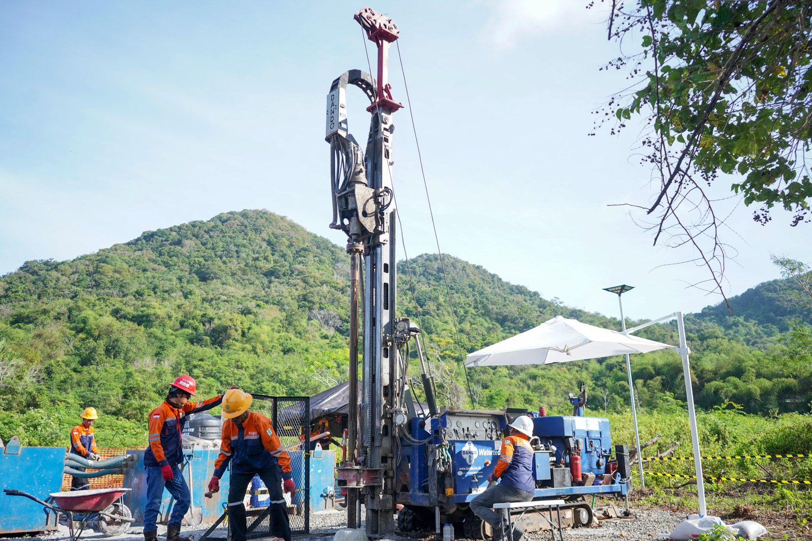
Drilling operations constitute most visible construction phase, progressively advancing borehole from surface to target depth while systematically documenting geological conditions, collecting formation samples, monitoring drilling parameters, and implementing safety protocols protecting personnel and preventing environmental contamination. Drilling duration varies substantially with depth (typically 10-30 meters per day for consolidated formations, 30-100 meters daily in soft sediments), geological conditions particularly hard rock or unstable formations requiring slower advancement, drilling method employed, and operational efficiency including equipment reliability and crew proficiency, with typical production well drilling requiring 3-15 days for depths 50-200 meters under favorable conditions.
Drilling method selection critically affects efficiency, borehole quality, formation disturbance, and ultimately well performance, with primary methods including rotary drilling using bentonite mud circulation providing borehole stability through hydrostatic pressure and cuttings removal while forming thin filter cake on borehole wall limiting fluid loss, reverse circulation employing dual-pipe drill string with upward flow through center pipe enabling continuous sampling of large cuttings ideal for detailed geological logging, air rotary utilizing compressed air for cuttings removal in consolidated formations eliminating drilling fluid potentially damaging aquifer but limited to stable geological conditions above water table, and down-the-hole (DTH) hammer for hard rock applications where bit percussion combined with rotation achieves penetration rates in crystalline or well-cemented sedimentary rocks otherwise requiring slow progress. Method selection depends on geology with mud rotary universally applicable but potentially causing formation damage from mud invasion requiring thorough development, reverse circulation preferred for unconsolidated sediments enabling larger diameter holes with excellent sample quality supporting screen design optimization, air methods minimizing formation damage but restricted to appropriate geological settings, and combination approaches often optimal utilizing different methods for overburden penetration versus aquifer zone drilling.
Table 3: Drilling Method Comparison and Applicability Guidelines
| Drilling Method | Technical Description | Best Applications | Advantages | Limitations | Typical Cost Relative Index |
|---|---|---|---|---|---|
| Direct Rotary (Mud Circulation) |
Rotating drill bit, bentonite mud down drill pipe, returns up annulus carrying cuttings | Universal applicability, soft to medium formations, depths to 300m+, diameters 150-600mm | Versatile, borehole stability, cost-effective, widely available | Formation damage from mud invasion, small cuttings samples, development critical | 1.0 (baseline) |
| Reverse Circulation |
Dual-pipe string, water/mud down annulus, cuttings up center pipe via suction | Unconsolidated to semi-consolidated sediments, large diameter 300-900mm, detailed sampling needed | Excellent sample quality, faster penetration soft formations, less formation damage | Requires large water volume, limited hard rock capability, specialized equipment | 1.2-1.5 |
| Air Rotary (Compressed Air) |
Rotating bit, compressed air down drill pipe, cuttings blown up annulus | Consolidated formations above water table, fractured rock, diameters 150-400mm, depth to 200m | No formation damage, immediate water yield indication, fast penetration stable rock | Requires stable formations, limited below water table, dust control issues | 1.1-1.3 |
| Air Rotary with Foam/Mist |
Compressed air with surfactant foam or water mist enhancing cuttings lift | Consolidated formations below water table, higher yield aquifers, fractured rock | Works below water table, good formation preservation, yield indication during drilling | Requires stable geology, significant air compressor capacity, foam disposal | 1.2-1.4 |
| Down-the-Hole (DTH) Hammer |
Pneumatic hammer at bit, percussion with rotation, air circulation for cuttings | Hard rock (granite, basalt, limestone), fractured formations, diameters 150-350mm, depths to 300m | Fast penetration hard rock, straight boreholes, minimal formation damage | High equipment cost, requires large compressor (20-30 bar), limited soft formations | 1.4-1.8 |
| Cable Tool (Percussion) |
Heavy bit repeatedly dropped, cuttings bailed periodically, casing driven as drilled | Boulder formations, unstable ground, small diameter shallow wells, confined space | Handles boulders/unstable ground, no formation damage, simple equipment | Very slow (5-15m/day), limited depth (typically <150m), labor intensive | 1.5-2.5 |
Cost index relative to direct mud rotary baseline; actual costs vary with geology, depth, diameter, site access, equipment mobilization. Method selection prioritizes technical suitability over cost, as appropriate method for geological conditions ensures quality well construction, adequate development, optimal long-term performance justifying potential 10-30% cost differential between methods.
Geological logging constitutes essential drilling activity systematically documenting subsurface conditions at regular intervals typically every 0.5-1.0 meter depth, recording lithology (sediment or rock type, texture, color, cementation), mineralogy, water-bearing characteristics, fracture density and orientation in rock, and drilling characteristics providing qualitative formation strength indication. Logging methodology depends on drilling method with cuttings samples from rotary drilling examined at surface identifying major lithological units but limited fine-detail resolution due to sample mixing and lag time, continuous core samples from wireline coring providing highest-quality information but requiring specialized equipment and slower advancement rarely justified for production wells except geological uncertainty situations, and downhole geophysical logs after drilling completion providing quantitative formation properties including natural gamma radiation indicating clay content, resistivity correlating with porosity and water quality, spontaneous potential identifying permeable zones, caliper measuring borehole diameter detecting washouts or cave-ins, and temperature/fluid conductivity profiling delineating water-bearing zones supporting optimized screen placement decisions.
Phase 5: Well Completion - Casing, Screen, and Grout Installation
Well completion encompasses critical construction activities transforming open borehole into functional, protected water well through installation of properly selected and configured casing providing structural integrity and sanitary protection, well screen optimizing hydraulic connection to productive aquifer zones, filter pack surrounding screen preventing sand entry while maintaining hydraulic efficiency, and annular grout seal isolating aquifer from surface contamination and preventing vertical migration between aquifer zones. Completion typically requires 2-5 days depending on well depth and complexity, with specialized installation procedures, quality verification, and curing time ensuring proper function throughout anticipated 25-50 year service life.
Casing installation begins immediately upon reaching target depth before borehole stability degradation occurs, with casing string assembled at surface through threaded connections or welding (steel casing) following manufacturer specifications ensuring water-tight joints able to withstand handling stresses, earth pressures, and tensile loads during installation. Installation method depends on borehole condition and casing material, with stable boreholes accommodating simple lowering of casing string suspended from hoist or crane maintaining central alignment through guides or centralizers at regular intervals typically every 6-9 meters (20-30 feet), unstable or collapsing formations potentially requiring casing drive method where heavy-wall drive casing advances ahead of or simultaneously with drilling providing continuous borehole support, and telescoping casing design reducing diameter at depth enabling penetration through difficult zones while maintaining adequate final diameter for pump installation. Critical installation considerations include maintaining verticality within tolerance typically 1-2 degrees from vertical over total depth preventing pump installation difficulties or wear, verifying depth measurement ensuring screen placement at intended aquifer zones, and documenting final configuration for record purposes.
Figure 2: Standard Production Well Completion Schematic - Vertical Section with Component Details
Surface Completion Zone (0 to -15 meters)
Surface Seal & Wellhead (0 to -1.0m):
• Concrete pad: Minimum 1.0m x 1.0m x 0.15m thick, sloped away from well for drainage
• Surface casing extension: 0.3-0.6m above grade, vented sanitary well cap with screened vent
• Well identification: Permanent marker showing well number, depth, installation date
• Access protection: Lockable cap or well house preventing unauthorized access/contamination
• Drainage: Swale or drain directing surface water away from wellhead minimum 3m radius
Annular Grout Seal (-1.0m to -15m minimum, deeper preferred):
• Material: Neat cement (Portland Type I/II), bentonite-cement mix (5-10% bentonite), or specialized well grout
• Minimum thickness: 50-75mm (2-3 inches) annular space for gravity placement, thicker if tremie grouted
• Placement method: Tremie pipe from bottom up preventing bridging, ensuring continuous seal
• Function: Prevents surface contamination reaching aquifer, isolates casing from formation, structural support
• Depth requirement: Minimum 15m or through all unconsolidated overburden into competent formation
• Regulatory: SNI 6469:2012 requires minimum 15m seal depth; international standards often 20-30m
Intermediate Zone (-15m to top of aquifer)
Blank Casing Through Non-Productive Formations:
• Material: PVC Schedule 40/80, HDPE, or steel (carbon/stainless) per design specifications
• Wall thickness: Adequate for collapse resistance, handling loads, and internal pressure
• Joint type: Flush-threaded or welded (steel), solvent-welded or gasketed (PVC), butt-fusion (HDPE)
• Function: Structural integrity maintaining open borehole, prevents inflow from non-target zones
• Annular space: May be filled with filter sand if grouting impractical at depth, or left open in stable formations
• Centralizers: Installed every 6-9m maintaining alignment, ensuring uniform annular space
Aquifer Production Zone (Variable depth per site geology)
Upper Transition: Blank Casing in Low-Permeability Zone:
• Length: 1-3 meters blank casing above screen entrance ensuring pump submergence
• Purpose: Prevents pump intake in screened interval, provides stable setting for pump
Well Screen - Primary Water Entry Component:
• Screen type: Continuous-slot wire-wound (8-12% open area) or slotted PVC/steel (3-6% open)
• Slot size: Typically 0.5-2.0mm (0.020-0.080") selected based on aquifer grain size analysis
• Screen length: 50-80% of productive aquifer thickness for confined aquifers, 30-50% unconfined
• Placement: Positioned via careful depth measurement, verified by geophysical logs if available
• Centralizers: Bottom and intervals along screen maintaining alignment, uniform filter pack
• Entrance velocity: Design target <0.03 m/s (0.1 ft/s) minimizing head loss and sand entrainment
Filter Pack (Gravel Pack) Surrounding Screen:
• Material: Graded silica sand or gravel, well-rounded, uniform grain size
• Sizing: D50 of pack 4-6 times D50 of formation (natural pack) or selected for screen slot retention
• Thickness: Minimum 75mm (3"), typically 100-150mm (4-6") around screen for hydraulic efficiency
• Placement: Tremied from bottom up or poured carefully preventing bridging/segregation
• Height: Extends 1-2 meters above screen top, transitions to bentonite seal or formation material
• Function: Prevents formation sand entering well, stabilizes borehole wall, increases effective well radius
Lower Transition: Blank Casing Below Screen (if required):
• Length: 1-5 meters or to borehole total depth
• Purpose: Sump for sediment accumulation, stabilizes screen assembly during installation
• Bottom cap: May include drive shoe if casing driven, or simple cap if lowered into borehole
Bottom Zone (Below aquifer to total depth)
Sump or Blank Casing Extension:
• Function: Collects sediment preventing screen clogging, provides below-screen stability
• Length: Typically 2-5m below screen, may extend to total drilled depth
• Clean-out: Accessible for periodic sediment removal via bailer or airlift during maintenance
TYPICAL WELL DIMENSIONS EXAMPLE:
Total Depth: 120 meters | Aquifer Depth: 80-110m | Casing: 8-inch (200mm) PVC Schedule 80
Screen: 6-inch (150mm) stainless wire-wound, 20 meters length (80-100m depth), 1.0mm slot
Filter Pack: 150mm thickness, 2-4mm silica sand | Grout Seal: 0-30m depth, neat cement
Design Capacity: 20 L/s (72 m³/hour) with 15m drawdown @ specific capacity 1.3 L/s/m
Grout seal installation represents most critical well sanitary protection component, utilizing cement-based or bentonite-based materials placed in annular space between casing and borehole wall forming continuous impermeable barrier preventing surface contaminants reaching aquifer and isolating aquifer from overlying formations. Grout placement methodology profoundly affects seal integrity, with tremie pipe method representing best practice standard where grout delivery pipe extends from surface to bottom of zone being grouted with grout pumped through pipe displacing drilling fluid or water upward as grout rises from bottom preventing bridging or voids that compromise seal, contrasted with less reliable pour-from-surface method acceptable only shallow depths under 10-15 meters where short drop distance and slow pour rate enable continuous grout column. Grout material selection depends on application with neat cement (Portland cement Type I or II mixed with water at 5-6 gallons per 94-pound bag, yielding approximately 1.2 cubic feet) providing maximum strength and durability for permanent seals, bentonite-cement mix (typically 5-10% bentonite by weight of cement) offering advantages of lower shrinkage, self-healing characteristics if minor cracking occurs, and reduced permeability though lower compressive strength than neat cement, and specialized well grouting products available providing engineered properties for specific conditions including high-sulfate cements for aggressive groundwater, expanding cements compensating shrinkage, or thermally-conductive grouts for geothermal applications.
Phase 6: Well Development and Hydraulic Performance Testing
Well development constitutes essential post-completion activity removing drilling-induced formation damage, fine particles, and drilling fluid residues from near-wellbore zone, rearranging aquifer materials around screen openings establishing natural filter preventing sand production, and maximizing hydraulic connection between well and aquifer achieving optimal specific capacity and long-term productivity. Development typically requires 1-3 days continuous effort for routine wells potentially extending to 5-7 days for difficult conditions, utilizing various mechanical and hydraulic techniques progressively removing damage until water quality parameters (turbidity, sand content) and well yield stabilize indicating development completion and readiness for performance testing establishing operational parameters.
Development methods employ various approaches often combined in sequence targeting different damage mechanisms, with overpumping representing most common technique where well pumped at rates 150-300% of anticipated operational yield creating high velocity through screen drawing fines from formation into wellbore for removal, airlifting utilizing compressed air injected through pipe to water depth lifting water and sediment to surface through airlift action particularly effective removing fine drilling mud residues and loosening compacted material around screen though requiring substantial air compressor capacity typically 250-350 cfm at 100-150 psi for 6-8 inch wells, surging employing surge plunger or block moved vertically in casing above screen creating alternating positive and negative pressure pulses loosening formation materials and breaking down drilling mud filter cake, and high-velocity jetting where water or air under pressure directed through nozzles across screen face physically removing particles and breaking up compacted zones. Sequential development strategy typically begins with gentle airlifting or low-rate pumping removing easily mobilized fines, progresses through increasingly aggressive techniques including surging and higher pumping rates addressing more resistant damage, and concludes with extended pumping at design rate until water quality parameters meet acceptance criteria typically turbidity below 5-10 NTU and sand content under 5-10 mg/L (ppm) on 100-mesh screen analysis.
Table 4: Step-Drawdown and Constant-Rate Pumping Test Procedures and Analysis
Step-Drawdown Test Protocol
Purpose: Determine well efficiency, screen entrance losses, optimal pumping rate, and turbulent flow characteristics
| Step Number | Pumping Rate (% of estimated capacity) |
Duration (hours) |
Measurements | Analysis Purpose |
|---|---|---|---|---|
| Step 1 | 25-33% | 1-2 hours | Water level every 5 min, flow rate every 15 min, final stabilized drawdown | Establish baseline linear aquifer losses |
| Step 2 | 50-67% | 1-2 hours | Water level every 5 min, flow rate every 15 min, final stabilized drawdown | Identify onset of turbulent losses |
| Step 3 | 75-100% | 1-2 hours | Water level every 5 min, flow rate every 15 min, final stabilized drawdown | Quantify nonlinear well losses |
| Step 4 (optional) |
125-150% | 1-2 hours | Water level every 5 min, monitor sand production, cavitation indicators | Define maximum safe capacity |
Analysis Method:
1. Plot specific drawdown (s/Q) versus discharge rate Q on linear or log-log scale
2. Calculate well loss coefficient using Jacob's method: s = BQ + CQ² where B = aquifer loss, C = well loss
3. Determine well efficiency: η = BQ/(BQ + CQ²) × 100%, target >70-80% indicating good development
4. Identify optimal operating rate where efficiency maximized, typically 60-80% maximum tested capacity
5. Check sand production indicators: turbidity spike, abrasion sounds, visual inspection for sand content
Constant-Rate Pumping Test Protocol
Purpose: Establish sustainable yield, aquifer hydraulic properties (transmissivity, storativity), boundary conditions, and long-term water level response
| Test Phase | Duration | Activities and Measurements | Data Analysis |
|---|---|---|---|
| Pre-Test Prep | 2-4 hours | Measure static water level, install monitoring equipment (transducers, flow meter), verify discharge location prevents recirculation, calibrate instruments | Establish baseline conditions, confirm equipment function |
| Pumping Phase | 24-72 hours (minimum 24h) |
Constant discharge at optimal rate from step test, water level measurements: every 1 min first 10 min, every 5 min to 100 min, every 15-30 min thereafter, continuous flow measurement, periodic water quality sampling (hourly to 4-hourly) | Plot time-drawdown on semi-log, identify aquifer type (confined/unconfined), calculate transmissivity using Theis, Cooper-Jacob, or appropriate method, assess boundary effects from deviations |
| Recovery Phase | 50-100% of pumping duration | Stop pump, immediately begin measuring water level recovery: every 1 min first 10 min, every 5 min to 100 min, every 15-30 min until 80-90% recovery, record time to full recovery | Plot residual drawdown vs. t/t', calculate storativity, verify transmissivity estimates, assess aquifer boundaries/recharge |
Acceptance Criteria:
• Drawdown stabilization: Change <3-5% over final 4 hours indicating sustainable pumping
• Specific capacity: Meets or exceeds design target (typical range 1-50 m³/h/m depending on aquifer)
• Water quality: Turbidity <5-10 NTU, sand content <5-10 ppm, bacteriological/chemical within limits
• No excessive drawdown: Pumping level stays above pump intake by minimum 3-5 meters
• Observation well response: If available, confirms aquifer response matches theoretical expectations
• Recovery: Returns to ≥90% of static level within reasonable time (1-2 times pumping duration typical)
Testing represents investment typically 5-12% of total well construction cost but provides essential data for pump selection, operating schedule optimization, aquifer management planning, and regulatory compliance documentation justifying thorough execution and professional analysis by qualified hydrogeologist or groundwater engineer.
Phase 7: Commissioning, System Integration, and Final Documentation
Commissioning phase transforms tested well into fully operational water supply system through pump and equipment installation, electrical and control system integration, final water quality verification meeting regulatory standards, comprehensive documentation compilation, operator training, and regulatory inspection achieving final acceptance and authorization for service commencement. This final phase typically requires 1-2 weeks depending on system complexity, with activities coordinated among well contractor, pump supplier/installer, electrical contractor, water treatment specialist if required, facility operators, and regulatory inspectors ensuring seamless transition from construction to reliable operation.
Pump selection and installation must match well hydraulic characteristics established through testing while meeting operational requirements for discharge pressure, flow control, efficiency, and reliability. Submersible turbine pumps represent standard choice for production wells offering advantages including prime-less operation eliminating priming systems required for surface pumps, quiet operation with motor and impellers submerged in well, efficient installation utilizing well casing itself as pump chamber eliminating separate pump house requirements, and protection from freezing or vandalism. Pump sizing calculations utilize test-established drawdown characteristics, required discharge pressure accounting for elevation change and distribution system head requirements, safety factors accommodating potential water level declines or increased demand, and specific speed considerations affecting efficiency and cavitation susceptibility. Installation procedures include lowering pump column assembly with discharge pipe, power cable, and control wiring through casing to setting depth typically 3-5 meters below anticipated pumping level ensuring adequate submergence under all operating conditions, connecting discharge piping with appropriate fittings enabling maintenance removal, installing check valve preventing reverse flow and water hammer, and setting pitless adapter or wellhead discharge configuration providing frost-free connection to distribution system.
Final Commissioning Checklist and Documentation Package
1. Well Construction Documentation (Critical Records):
- As-built construction diagram: Scaled vertical section showing all completion details: casing/screen depths, diameters, materials, grout seal extent, filter pack zones, sump depth, total depth, with measurements verified during construction
- Driller's log: Detailed lithological description every 0.5-1.0m depth interval, drilling method and parameters, fluid loss zones, water strikes, casing installation depths, completion materials quantities
- Geophysical logs: Natural gamma, resistivity, spontaneous potential, caliper, temperature/conductivity if conducted, with interpretation identifying aquifer zones, lithology correlation, screen placement justification
- Material certifications: Mill test reports or certificates of compliance for casing (pressure rating, material grade, dimensions), screen (slot size, open area, material), grout (cement type, mix design, compressive strength), filter pack (grain size analysis, uniformity coefficient, mineralogy)
- Video inspection log: Downhole camera survey documenting casing/screen integrity, alignment, joint condition, grout seal verification if visible, with timestamped footage and written narrative
2. Hydraulic Testing Documentation:
- Step-drawdown test report: Test procedure description, discharge rates and durations for each step, time-drawdown data tables and graphs, specific drawdown analysis, well efficiency calculation, optimal pumping rate recommendation
- Constant-rate test report: Test duration and discharge rate, complete time-drawdown and recovery data with measurements frequency noted, aquifer analysis methodology (Theis, Cooper-Jacob, etc.), calculated hydraulic parameters (transmissivity, storativity, hydraulic conductivity), boundary condition interpretation, sustainable yield determination
- Water level monitoring data: Static water level measurement, drawdown stabilization curve, recovery curve, maximum drawdown reached, specific capacity (m³/h per meter drawdown), comparison to design predictions
3. Water Quality Certification:
- Comprehensive laboratory analysis: Bacteriological testing (total coliform, E. coli, heterotrophic plate count) by ISO 17025 accredited lab, chemical parameters (major ions, hardness, iron, manganese, nitrate, fluoride, arsenic, heavy metals per drinking water standards), physical parameters (pH, turbidity, color, taste, odor, temperature), compared against Indonesian Permenkes No. 2/2023 drinking water standards or applicable industrial water specifications
- Sampling protocol documentation: Sampling location, date/time, preservation methods, chain of custody, laboratory accreditation confirmation, field parameters measured in situ (pH, temperature, dissolved oxygen, electrical conductivity)
- Water treatment recommendations: If water quality parameters exceed standards, specify required treatment processes (filtration, disinfection, aeration, ion exchange, reverse osmosis, etc.) with preliminary sizing and cost estimates
4. Pumping System Documentation:
- Pump specifications: Manufacturer, model, serial number, rated capacity and head, motor horsepower, voltage/phase, efficiency curve, materials of construction, recommended operating range
- Installation record: Setting depth, discharge pipe material and diameter, power cable type and length, control wiring, check valve location, pitless adapter or wellhead configuration, torque wrench settings for threaded connections
- Control system: Pressure switch or transducer settings, variable frequency drive (VFD) programming if applicable, level controls, alarm setpoints (low level, high temperature, overcurrent), remote monitoring configuration
- Manufacturer literature: Installation manual, operation and maintenance guide, parts list, warranty terms (typical 1-2 years on pump, 5-10 years on motor), service contact information
5. Operations and Maintenance Manual:
- Routine operation procedures: Startup sequence, normal operating parameters to monitor, shutdown procedures, seasonal adjustments
- Preventive maintenance schedule: Daily checks (operating hours, pressure, flow, unusual sounds), weekly inspections (electrical connections, controls, piping), monthly tasks (water level measurement, water quality field testing), annual activities (comprehensive water quality analysis, pump performance curve verification, electrical testing)
- Troubleshooting guide: Common problems (reduced yield, sand production, low pressure, high power consumption, pump noise), probable causes, corrective actions, when to contact service technician
- Record keeping forms: Daily operations log, maintenance activity record, water quality test results, repair history, parts replacement tracking
6. Regulatory Compliance Documentation:
- Groundwater extraction permit: Approved permit document specifying authorized withdrawal volume (daily/monthly/annual limits), monitoring requirements, reporting frequency, renewal date, compliance conditions
- Construction completion certificate: Certification by driller and supervising engineer that well constructed per approved design and applicable standards (SNI 6469:2012, AWWA A100-21), meeting regulatory requirements
- Water quality clearance: Health department or designated authority approval for potable use if applicable, or confirmation water meets intended use standards (industrial process, irrigation, etc.)
- As-built survey: Well location coordinates (GPS or survey grade), elevation reference, site plan showing well position relative to potential contamination sources (septic systems, fuel storage, animal facilities) with setback distances verified complying with protective distance requirements
Quality Assurance and Quality Control Throughout Construction
Comprehensive QA/QC program implementation throughout well construction proves essential ensuring completed facility meets design specifications, performance objectives, and regulatory requirements while providing framework for accountability, deficiency identification and correction, and documented verification supporting warranty claims or dispute resolution if construction problems emerge. Effective QA/QC encompasses both formal inspection procedures at critical construction milestones and continuous monitoring of contractor activities, materials quality, workmanship standards, and safety compliance, requiring dedicated oversight by qualified construction supervisor or well construction inspector with appropriate technical knowledge, experience, and authority to stop work if serious deficiencies identified requiring correction before proceeding.
Table 5: Critical Quality Control Inspection Points and Verification Procedures
| Construction Phase | Critical Inspection Points | Verification Methods | Acceptance Criteria / Standards |
|---|---|---|---|
| Pre-Drilling | Site preparation, equipment condition, materials delivery verification | Visual inspection of rig capacity, safety equipment, material certifications review, survey confirms well location | Rig meets depth/diameter specifications, materials match approved specifications with valid certifications, location surveyed within 1-2 meters of design position |
| Drilling Operations | Borehole diameter maintenance, verticality, depth measurement, geological logging accuracy | Caliper log or physical measurement, plumb bob or inclinometer survey, certified tape measure, geologist verification of lithology descriptions | Diameter within design tolerance (+5-10%), verticality <2° deviation over depth, depth measurement ±0.3m accuracy, continuous geological log every 0.5-1.0m |
| Casing Installation | Casing material verification, thread integrity, joint assembly, verticality, final depth | Material certification check, visual thread inspection, torque wrench verification or witness joint assembly, plumb check, measured depth tape | Materials match specifications (wall thickness, grade), threads clean without damage, joints torqued to manufacturer spec, casing vertical within tolerance, depth at design ±0.3m |
| Screen Placement | Screen type/slot size, positioning at target aquifer depth, centralizer installation, joint integrity | Slot size physical measurement (wire gauge or calipers), depth measurement during installation, centralizer spacing verification, video camera inspection if critical | Screen slot matches grain size analysis selection (±0.1-0.2mm), positioned per geological log and geophysical interpretation (±0.5-1.0m), centralizers every 6-9m, no damage |
| Filter Pack | Material grain size verification, placement method, volume calculation, settlement check | Sieve analysis of pack material sample, witness tremie placement or careful pouring, calculate expected volume vs. actual used, tagged line depth check | Grain size meets design (D50 and uniformity coefficient), clean sand without fines or organics, volume within 10-15% of calculated annular space, top of pack 1-2m above screen |
| Grout Seal | Grout mix design, placement method, volume, continuity verification, curing time | Mix design confirmation (water:cement ratio, additives), witness tremie placement from bottom up, volume calculation vs. actual used, temperature log or tag line check for top, minimum cure time enforcement | Neat cement or bentonite-cement per specification, tremie placement prevents bridging/voids, volume 90-110% of calculated annular space, seal extends minimum 15m depth (SNI) or per design, 48-72 hour cure before development |
| Well Development | Development technique sequence, duration, water quality improvement, yield stability | Observation of techniques employed and sequence, time log, turbidity meter readings, sand content samples on 100-mesh screen, flow measurement | Multiple techniques used (airlifting, surging, overpumping), minimum 8-24 hours total development time, turbidity <5-10 NTU final, sand <5-10 ppm, yield stable within 5% over final hours |
| Pumping Tests | Equipment calibration, measurement frequency compliance, test duration, data quality | Instrument calibration certificates, review data logger or manual records for proper intervals, verify test duration meets minimum, check data for gaps or anomalies | Flow meter ±3-5% accuracy, water level ±5-10mm accuracy, measurements at specified intervals without gaps, step test minimum 1-2 hours per step, constant-rate minimum 24 hours, recovery monitored 50-100% of pumping time |
| Water Quality | Sampling protocol compliance, laboratory accreditation, analysis completeness, results interpretation | Witness sampling procedure, verify chain of custody documentation, confirm laboratory ISO 17025 accreditation, review analytical report completeness and detection limits | Proper sampling technique (adequate purging, appropriate containers/preservation), accredited laboratory used, all required parameters analyzed with appropriate detection limits, results meet Permenkes No. 2/2023 drinking water standards or applicable specifications |
| Pump Installation | Pump specification match, setting depth, electrical installation safety, control configuration | Verify pump nameplate data vs. specifications, measure setting depth, electrical inspection per national electrical code, test controls functionality | Pump capacity/head matches design requirements, set 3-5m below minimum pumping level, electrical installation meets safety codes, controls operate properly including safeties (low level, overcurrent, etc.) |
| Final Documentation | Completeness of as-built records, test reports, certifications, operations manual | Review documentation package against checklist, verify accuracy of as-built diagram against field measurements, confirm all certifications included | Complete documentation per commissioning checklist, as-built accurate within ±0.5m of actual construction, all material certifications included, O&M manual provided with manufacturer literature, regulatory submittals complete |
Hold points: Construction should not proceed past critical phases until inspector approval obtained: (1) After drilling completion before casing installation, (2) After casing installation before grouting, (3) After grout cure before development, (4) After development before pumping tests, (5) After testing before pump installation. Non-compliance with acceptance criteria requires correction before proceeding; repeated deficiencies may warrant contractor replacement.
Cost Analysis and Economic Considerations
Well construction costs vary substantially based on depth, diameter, geological conditions, site accessibility, materials specifications, regional labor and equipment rates, and project-specific requirements including testing intensity and documentation standards. Indonesian production well construction typically ranges IDR 8,000,000-25,000,000 per meter total depth (approximately USD 500-1,600 per meter at exchange rate IDR 15,600 per USD), translating to complete 100-meter well costs approximately IDR 800,000,000-2,500,000,000 (USD 51,000-160,000) including mobilization, drilling, completion materials, development, testing, pump installation, and commissioning. Cost components break down approximately: drilling operations 35-45% (rig mobilization, daily drilling rates, drilling fluids, cuttings disposal), materials 25-35% (casing, screen, filter pack, grout), testing and development 10-15% (pumping test duration, water quality analysis, geophysical logging), pump and equipment 15-25% (submersible pump, power cable, discharge piping, controls), and engineering/oversight 5-10% (design, specifications, construction supervision, documentation).
Table 6: Typical Production Well Construction Cost Breakdown - 100 Meter Example
| Cost Category | Description / Specifications | Unit Cost | Total Cost (IDR) |
|---|---|---|---|
| MOBILIZATION AND SITE PREPARATION | |||
| Rig mobilization/demobilization | Transport drilling rig, support equipment, materials to site and return | Lump sum | 35,000,000 |
| Site preparation | Leveling, access road, drilling pad, water supply for drilling operations | Lump sum | 15,000,000 |
| DRILLING OPERATIONS | |||
| Drilling 0-30m (overburden) | 250mm diameter, rotary mud drilling, soft sediments, 30 meters | IDR 800,000/m | 24,000,000 |
| Drilling 30-100m (aquifer) | 250mm diameter, rotary drilling, medium consolidated, 70 meters | IDR 1,200,000/m | 84,000,000 |
| Geological logging | Continuous lithological description, sampling, documentation | Included | — |
| Drilling fluids and additives | Bentonite, polymers, water for circulation, disposal | Lump sum | 22,000,000 |
| WELL COMPLETION MATERIALS | |||
| PVC casing 8-inch Schedule 80 | 200mm (8") PVC Sch 80, 70 meters blank casing with threaded joints | IDR 950,000/m | 66,500,000 |
| Stainless screen 6-inch | 150mm (6") wire-wound stainless 304, 1.0mm slot, 20 meters | IDR 1,850,000/m | 37,000,000 |
| Filter pack (gravel pack) | Silica sand 2-4mm, 3 cubic meters around 20m screen zone | IDR 2,500,000/m³ | 7,500,000 |
| Annular grout seal | Neat cement, 0-30m depth, 2.5 m³ total volume, tremie placed | IDR 3,800,000/m³ | 9,500,000 |
| Surface seal and wellhead | Concrete pad 1m x 1m x 0.15m, sanitary well cap, identification marker | Lump sum | 8,500,000 |
| DEVELOPMENT AND TESTING | |||
| Well development | Airlifting, surging, overpumping, 2-3 days continuous effort | Lump sum | 28,000,000 |
| Geophysical logging | Natural gamma, resistivity, caliper, SP, temperature logs | Lump sum | 35,000,000 |
| Video camera inspection | Downhole camera survey, recording, written report | Lump sum | 18,000,000 |
| Step-drawdown test | 4 steps, 1.5 hours each, equipment rental, data analysis | Lump sum | 22,000,000 |
| Constant-rate pumping test | 48 hours pumping + recovery, instrumentation, analysis report | Lump sum | 45,000,000 |
| Water quality analysis | Comprehensive bacteriological, chemical, physical by accredited lab | Lump sum | 12,000,000 |
| PUMP INSTALLATION AND COMMISSIONING | |||
| Submersible pump 6-inch | 15 HP, 20 L/s capacity, 80m head, stainless steel construction | Lump sum | 85,000,000 |
| Installation accessories | Discharge pipe, power cable 100m, splice kit, check valve, fittings | Lump sum | 35,000,000 |
| Electrical and controls | Starter panel, pressure switch/transducer, level control, protection devices | Lump sum | 28,000,000 |
| Commissioning and training | System startup, verification, operator training, documentation | Lump sum | 15,000,000 |
| ENGINEERING AND PROJECT MANAGEMENT | |||
| Design and specifications | Hydrogeological investigation, well design, construction drawings | Lump sum | 45,000,000 |
| Construction supervision | Full-time inspector during construction, QA/QC implementation | Lump sum | 55,000,000 |
| Documentation and reporting | As-built drawings, test reports, O&M manual, regulatory submittals | Lump sum | 18,000,000 |
| SUBTOTAL | 750,000,000 | ||
| Contingency (10-15%) | 90,000,000 | ||
| TOTAL PROJECT COST | IDR 840,000,000 (~USD 54,000) |
||
| Unit Cost per Meter Depth | IDR 8,400,000/m (~USD 540/m) |
||
| Lifecycle Water Cost (25-year life, 300 days/year operation, 20 L/s average) | IDR 1,300/m³ (~USD 0.083/m³) |
||
Costs based on 2024-2025 Indonesian market conditions for medium-complexity site with good access, stable geology, moderate aquifer depth. Actual costs vary ±20-40% depending on site-specific factors: remote location (+15-30%), difficult geology like hard rock or unstable formations (+20-40%), larger diameter 12-16 inch (+30-60%), greater depth 150-300m (+15-25% per 100m increment), premium materials like stainless casing (+40-80%), extended testing 72+ hours (+10-20%). Lifecycle cost calculation includes: capital amortized over 25 years at 8% discount rate, electricity IDR 1,450/kWh, maintenance 3% of capital annually, pump replacement every 10 years, operator labor, monitoring/compliance costs.
Common Construction Problems and Solutions
Despite careful planning and quality contractors, well construction inevitably encounters challenges from geological surprises, equipment limitations, weather delays, or unforeseen site conditions requiring adaptive management, technical problem-solving, and sometimes design modifications ensuring successful completion. Understanding common problems, their causes, and proven solutions enables project teams respond effectively minimizing delays and cost impacts while maintaining construction quality and final well performance meeting design objectives.
Common Well Construction Problems: Causes and Solutions
Problem 1: Borehole Collapse or Caving
Symptoms: Drill pipe stuck, unable to remove drill string, loss of drilling fluid circulation, drill cuttings falling back into borehole
Common causes: Unconsolidated formations (loose sand, gravel), fractured or weathered rock, inadequate drilling fluid properties or hydrostatic pressure, drilling too fast without proper fluid conditioning, leaving hole open too long before casing
Prevention: Adjust drilling fluid properties (increase density/viscosity), slow drilling rate allowing proper borehole stabilization, minimize open-hole time by casing promptly after reaching target depth, consider casing-while-drilling for severely unstable conditions
Solutions if occurs: Condition drilling fluid (add bentonite, polymers increasing viscosity), work pipe up/down gently to free if stuck, consider setting temporary casing or liner through unstable zone, if severe collapse may require abandoning hole section and drilling new borehole, install casing quickly once unstable zone passed
Problem 2: Lost Circulation (Drilling Fluid Loss)
Symptoms: Drilling fluid level drops in borehole, no or reduced returns to surface, rapid fluid loss requiring continuous makeup
Common causes: Highly permeable formations (coarse gravel, fractured rock, karst cavities), induced fracturing from excessive mud weight or pump pressure, natural voids or solution channels
Prevention: Reduce drilling fluid pressure when entering known permeable zones, use appropriate fluid properties minimizing formation damage while maintaining borehole stability
Solutions if occurs: Add lost circulation materials (LCM) to drilling fluid: coarse particles (walnut shells, ground corn cobs, mica flakes), fibrous materials (shredded paper, wood fiber), or specialized bentonite-based plugging agents, pump cement or bentonite slurry to plug severe loss zones, consider air drilling methods if continued fluid loss uncontrollable and formation stable enough, may be indicator of highly productive aquifer zone (positive development)
Problem 3: Deviation from Vertical (Crooked Hole)
Symptoms: Difficulty installing casing (tight spots, binding), pump installation problems, accelerated wear on rods or cables from rubbing
Common causes: Drilling across dipping rock layers or bedding planes, soft/hard formation interbeds causing drill bit deflection, improper drill string weight or rotation speed, worn or bent drill pipe
Prevention: Use proper drilling parameters (weight, rotation speed), employ stabilizers in drill string maintaining alignment, rotate drill string continuously rather than sliding, conduct periodic deviation surveys (especially depths >100m) allowing corrective action if deviation detected early
Solutions if occurs: If detected early (deviation <2-3°), may self-correct with drilling parameter adjustment and stabilizers, severe deviation (>5-6°) may require reaming borehole to larger diameter accommodating casing installation, worst case abandon deviated section and drill new borehole with corrective measures, design pump installation accounting for deviation if within acceptable limits (typically maximum 3-4° total deviation acceptable for submersible pumps)
Problem 4: Aquifer Not Found or Lower Yield Than Expected
Symptoms: Little or no water entry during drilling, pumping tests show inadequate yield below design requirements
Common causes: Inaccurate preliminary investigation (geophysical misinterpretation, non-representative analogous well data), geological variability (aquifer pinches out or thins), drilling location not optimized, seasonal water table fluctuation affecting yield during testing, drilling-induced formation damage severe
Prevention: Invest in thorough site investigation (multiple geophysical stations, exploratory boring if high-value project), collect representative aquifer data during drilling (water strikes, flow estimates, geophysical logs), locate well at geologically favorable position identified through investigation
Solutions if occurs: Deepen well penetrating further into aquifer or reaching secondary deeper aquifer, intensive well development may improve yield if damage primary cause, consider artificial gravel pack or specialized screen if natural formation poor, install lower-capacity pump meeting available yield (revise system design to reduced capacity), worst case abandon well and drill new location based on improved geological understanding
Problem 5: Sand Production During Pumping
Symptoms: Visible sand in discharge water, pump abrasion/wear, turbidity spikes when starting pump or increasing rate, gradual yield decline from screen plugging
Common causes: Screen slot size too large for aquifer grain size, inadequate filter pack (wrong sizing, gaps in placement, bridging during installation), excessive pumping rate creating high entrance velocities, incomplete well development leaving loose fines, aquifer naturally unstable (very fine or poorly sorted sediments)
Prevention: Proper screen slot selection based on grain size analysis (retain 85-90% of formation), appropriate filter pack design and careful installation, adequate well development removing mobile fines, conservative pumping rate keeping entrance velocities <0.03 m/s
Solutions if occurs: Reduce pumping rate below threshold causing sand entrainment (may require accepting lower capacity), additional development effort may stabilize formation, consider well rehabilitation pulling pump and redeveloping, severe cases may require pulling casing and reinstalling with smaller screen slots and/or better filter pack, chronic sand production sometimes manageable through sand separators or settling tanks though indicates underlying problem
Problem 6: Grout Seal Problems (Voids, Bridging, Inadequate Seal)
Symptoms: Grout volume used much less than calculated annular space, temperature log shows cool spots indicating voids, surface contamination reaches aquifer, vertical flow between aquifers
Common causes: Improper placement method (pouring from surface in deep well), bridging in narrow annular space, excessive grout pumping rate causing turbulence and mixing with drilling fluid, inadequate centralization allowing casing against borehole wall, lost circulation during grouting
Prevention: Always use tremie pipe method starting from bottom of seal zone and withdrawing as grout rises, maintain continuous grout column during placement, calculate grout volume accounting for actual annular space (caliper log if available), use appropriate grout mix design and pumping rate, ensure casing centralized with adequate annular space (minimum 50-75mm), monitor grout returns and volumes carefully
Solutions if occurs: Temperature or other logs identify void locations enabling targeted remedial grouting, may require pressure grouting techniques for existing voids, serious seal deficiencies may necessitate regulatory notification and corrective action plan, worst case well abandonment and redrilling if seal critically compromised affecting water quality or cross-contamination
Glossary of Technical Terms
Annulus / Annular Space: Ring-shaped space between well casing and borehole wall, typically filled with grout seal or filter pack depending on depth and function
Aquifer: Geological formation containing saturated permeable materials (sand, gravel, fractured rock) capable of yielding economically significant water quantities to wells
Drawdown: Vertical distance water level lowered in well from static level due to pumping, measured in meters
Filter Pack / Gravel Pack: Layer of sized sand or gravel placed in annular space surrounding well screen, prevents formation sand entry while enhancing hydraulic efficiency
Grout: Cement-based or bentonite mixture placed in annular space forming impermeable seal preventing surface contamination and isolating aquifers
Lithology: Physical character of geological formation including rock or sediment type, texture, grain size, color, cementation, used to identify aquifer zones
Specific Capacity: Well yield per unit drawdown (m³/hour per meter or L/s per meter), indicates well productivity and aquifer transmissivity
Transmissivity: Aquifer hydraulic property quantifying water transmission rate through full saturated thickness under unit hydraulic gradient (m²/day), product of hydraulic conductivity and aquifer thickness
Tremie Pipe: Pipe extending from surface to placement depth enabling grout or filter pack delivery from bottom upward, preventing bridging and ensuring continuous seal
Well Development: Process of removing drilling-induced formation damage and fine particles through various mechanical and hydraulic techniques, maximizing well productivity
Technical References and Standards
International and Indonesian Standards for Professional Well Construction:
AWWA A100-21: Water Wells Standard
Comprehensive standard for water well design, construction, testing, and maintenance from American Water Works Association
NGWA Water Well Construction Standard 01-14
National Ground Water Association standard specifying minimum requirements for well construction, sealing, and documentation
https://www.ngwa.org/docs/default-source/what-is-ngwa/water-well-construction-standard.pdf
USDA NRCS Water Well Standard (Code 642)
US Department of Agriculture Natural Resources Conservation Service standard for agricultural and rural water supply wells
https://www.nrcs.usda.gov/sites/default/files/2023-09/642_OH_CPS_Water_Well_2023%20(1).pdf
EPA Design and Installation of Monitoring Wells
US Environmental Protection Agency comprehensive guidance on well design, construction materials, installation procedures
UFGS 33 11 13: Potable Water Supply Wells (US Military Specification)
Unified Facilities Guide Specification for military installation water supply well design and construction
SNI 6469:2012 - Sumur Pompa Dalam (Indonesian National Standard)
Indonesian national standard for deep well construction specifying minimum requirements for well design, construction, and testing applicable to Indonesian projects
Conclusions and Strategic Recommendations
Professional groundwater production well construction represents sophisticated multidisciplinary engineering undertaking requiring integration of hydrogeological sciences, advanced drilling technologies, materials engineering, quality assurance protocols, and regulatory compliance frameworks to deliver reliable, safe, and economically sustainable water supply systems. This comprehensive technical analysis demonstrates that systematic application of international best practices from AWWA, NGWA, EPA, and other authoritative sources, properly adapted to Indonesian geological conditions and regulatory requirements, enables construction of high-quality production wells achieving decades-long reliable service supporting municipal utilities, industrial facilities, commercial developments, and communities throughout Indonesian archipelago facing growing water supply demands amid competing resource pressures.
Success in professional well construction fundamentally depends on several critical factors: (1) thorough preliminary investigation establishing realistic design parameters through competent hydrogeological assessment, geophysical surveys, and where justified exploratory drilling or pump testing of analogous wells providing empirical performance data; (2) appropriate design specifications matching well configuration, materials, and completion methods to site-specific geological conditions, water quality characteristics, and operational requirements while incorporating adequate safety factors and regulatory compliance; (3) qualified contractor selection based on demonstrated technical capability, equipment adequacy, quality assurance commitment, and relevant experience rather than solely lowest-bid price which frequently correlates with shortcuts compromising well performance and longevity; (4) construction oversight implementing comprehensive QA/QC program with qualified inspection personnel having authority to verify compliance and require corrections before proceeding past critical construction phases; (5) adequate development and testing establishing well hydraulic performance, aquifer properties, and water quality characteristics supporting pump selection, operating schedule optimization, and regulatory compliance documentation; and (6) complete documentation providing permanent record supporting operations, maintenance, future rehabilitation planning, and regulatory requirements throughout well operational lifetime potentially spanning 30-50+ years.
For well owners and project developers, investment in professional well construction following international standards proves economically justified through multiple benefits including: higher and more reliable yields from properly designed and developed wells maximizing aquifer productivity, longer service life from quality materials and construction workmanship reducing replacement frequency, lower operating costs from efficient hydraulic design and appropriate pump sizing, reduced maintenance requirements and fewer unplanned repairs from proper completion preventing sand production and corrosion, regulatory compliance avoiding penalties and ensuring operating authorization, and documented performance supporting financial planning and asset management over extended operational periods. While initial capital costs for professional construction may exceed informal or substandard approaches by 20-40%, lifecycle economic analysis consistently demonstrates superior value through reduced operating costs, longer service life, and avoided premature replacement justifying quality construction investment.
For Indonesian water supply sector broadly, promoting professional well construction standards through education, training, regulatory enforcement, and industry capacity building would substantially improve groundwater development sustainability, protecting this critical resource while enabling reliable water supply supporting national development priorities. Recommended initiatives include: establishing or strengthening well driller certification programs ensuring technical competency and professional standards, developing Indonesian-language technical guidance documents translating international best practices to local context with appropriate examples and specifications, regulatory oversight ensuring construction quality through permit review, inspection programs, and enforcement of SNI 6469:2012 and other applicable standards, professional development programs for hydrogeologists, engineers, and drillers maintaining currency with developing technologies and methodologies, and public awareness campaigns educating well owners regarding importance of professional construction, proper operations, and maintenance requirements supporting long-term groundwater resource sustainability throughout Indonesian archipelago.

Professional Groundwater Drilling and Construction Development Services
SUPRA International provides comprehensive groundwater development consulting services for production well projects including hydrogeological site investigations, geophysical surveys, exploratory drilling programs, detailed well design and specifications, construction supervision and quality assurance, pump testing and aquifer analysis, water quality assessment, regulatory compliance support, and operational training. Our multidisciplinary team of hydrogeologists, groundwater engineers, and environmental specialists supports municipal utilities, industrial facilities, commercial developers, government agencies, and NGO projects throughout Indonesia, delivering technically sound, economically viable, and environmentally sustainable groundwater supply solutions meeting international standards while addressing site-specific challenges common in Indonesian geological and operational contexts.
Need expert assistance with groundwater well development?
Contact our technical specialists to discuss your water supply requirements, site conditions, and professional well construction services
Share:
If you face challenges in water, waste, or energy, whether it is system reliability, regulatory compliance, efficiency, or cost control, SUPRA is here to support you. When you connect with us, our experts will have a detailed discussion to understand your specific needs and determine which phase of the full-lifecycle delivery model fits your project best.